2021-02-21 - 2021-03-16

H30R1602 transistor.
Воткнув данную деталь в измеритель ёмкости, хоть таким образом и не наблюдая полную ёмкость её затвора (которая, при открытом канале, будет несколько больше), можно однако навскидку представить себе необходимую мощность схемы драйверов её затворов.
Надо заметить, что разработчики серьёзных схем явно не желают сталкиваться с эффектами даже от кратковременных зависаний транзистора в пограничном состоянии.
Посмотрите на схемы сварочных конвертеров: там, в качестве затворных драйверов, используются на однополярном напряжении 15В транзисторы IRFZ24 с номинальным током 17А.
The unconnected transistor has these capacitances between its gate and the other two pins: G-E 3.30nF, G-C 3.05nF, G-CE 5.45nF.
However, it is clear that the capacitance will change when the channel will become open.
Only very slightly depending on the load, it gets some value around 8.16nF when the transistor is fully open.
It is also clear that when the transistor does its inverter job, its capacitance does some little of a counter job, preventing it to be loaded smoothly: we might say the capacitance increases (has a spike) when the transistor is going close to saturation.
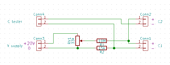
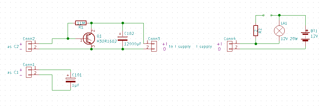
I've used ALDA DT890F as capacitance meter, because it gives the testing output of only a small magnitude (435Hz, 94mV, not changing under 6800pF being measured), in intention to get the measured results less spoiled.
The measuring scheme adds 0.35nF as initial error, thus subtract that value from what you see on the screen of a multimeter in the video.
The measured capacitance had peaks at:
C-E x.xxV/1.390A, G-E 7.63V/11.63(11.98-0.35)nF.
C-E 2.35V/4.800A, G-E 8.03V/12.71(13.06-0.35)nF.
The other value you might be also interested in is the voltage in the short state:
C-E 1.43V/5.27A, G-E 20V.
Conclusion about the power of gate driving scheme.
Normally, developers wouldn't want to debug various side effects due to gate not being enough quickly charged/discharged but staying too long in the transition state while producing various possible high freq pulses at that moment, which even are unstable and unpredictably appearing/disappearing depending on other subconditions.
Thus, lets say, in various welding converters, you may see a powerful transistors like IRFZ24/IRF9Z24 (of 17A max current) with +15V (unipolar) supply and a transformer as a gate driver scheme (4 such transistors and 1 transformer (of low power) per 4 IGBT transistors being driven).
You shouldn't even rely on the peak number for the capacitance which you see in this video: at the transition point and being under high current the capacitance might appear being even greater.
https://www.youtube.com/watch?v=CO5ALD8hZCk